Your Classified Ad Destination for Hutsville area > North Hutsville
> 24 x 1 lcd character display with hookup wire
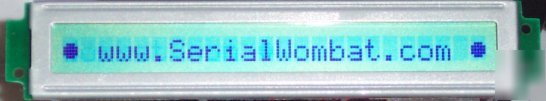
24 x 1 lcd character display with hookup wire
Additional Techincal Information:
The Serial Wombat supports this LCD directly. Just tell it through the RS-232 connection which LCD pins are attached to which Wombat pins, and what string to display. It's just that easy.
This LCD panel has a sticker on the back with the lettering WD-C2401P-1GNNa A81207-1 . Many sites refer to it without the hypen: WDC2401P or WDC2401 .
This LCD panel uses the Hitachi HD66717 dot-matrix lcd controller. You can get the datasheet for the controller here:
And the datasheet for this particular LCD display here:
Pros and Cons for the WD-C2401P LCD Panel:
Cheap! Only $2.95 per LCD display
Software controllable contrast (no external contrast voltage required)
Good documentation. Both the Pinout and the HD66717 controller documentation are readily available.
This LCD doesn't appear to flicker when you update it rapidly.
Up to four user programmable characters are available.
The connector is a single row of pins, .05 inch spacing. Good luck trying to find a connector. I soldered up a rats' nest in about 10 minutes.
Requires at least 10 I/O lines. There is no way to enable the serial or 4-bit parallel I/O modes in software.
The character set for this particular LCD appears to be custom; it is different from the character set displayed in the HD66717 manual. It substitues various international characters for graphics (which may be a "pro" for non-english speakers). I really wish there was a solid block in the character set.
I couldn't find a connector to fit this LCD's .05 center spacing, so I just soldered right to the pins. The LCD's pins are awfully close together:
So I bent every other one in opposite directions to make them easier to solder.
Soldering them up was a breeze. For newbies, put a bit of solder on each pin, then on each wire. Hold the wire to the pin, then melt them together with the iron. Get an iron with a thin pencil tip and some small diameter solder (.032) at Radio Shack or Fry's Electronics. Don't try to manage with an iron or solder from the hardware store; they're meant for electrical, not electronics work.
I like using one color for even numbered pins, one for odd. Makes it easier to hook up later:
Then I cover them up with epoxy so I don't pull them apart or short them together later. Use the Gel kind of epoxy; the other stuff just drips off before it can dry. Be careful not to put epoxy all the way down the connector to the circuit board. The spots where the pins attach to the board can be used later for debugging. Obviously, you want to make sure that all your wires are well soldered and not shorting pins together before you put on the epoxy.
When this pin is low it resets the LCD. You can either tie this pin to a pin on your microcontroller so you can reset the LCD before initializtion, or just tie it high. I had a couple of times where I couldn't init the LCD without first resetting it, so I'd recommend putting it under micro control, or some other powerup controller. The reset low time should be at least 10ms. The time after reset before you start commanding the LCD should also be at least 10 ms.
Register Select. This pin determines whether the data you're about to write is a command or a data byte. Commands do interesting stuff to the LCD, like set the number of lines or contrast. Data is what actually gets put on the screen, or in the custom character registers. High means Data, Low means command
Set this pin high to read from the display. Set this pin low to write to it. If you don't need to update the display super fast you can save an I/O line by just tying it to ground. Wait at least a millisecond between each command and data, though, since you can't query the busy status without read capability.
Enable. This line works to clock in data and commands. See the protocol section below.
Protocol for the Hitachi HD66717 WD-C2401P
The protocol for this LCD is pretty simple.
2. Set the RS line high if you're sending data, or low if your sending a command.
4. Put your data on the data lines (DB0 through DB7)
5. Set the E line low. The E line should remain low until you're ready to clock in another byte.
If you're using a microcontroller to do this, I'd make sure there was at least a microsecond between all of the above steps, and at least a millisecond between clocked in bytes. This is a long time to wait, but you want to be careful if you're hardwiring the Read/Write line low and not reading the busy status of the LCD.
Setting up the LCD to display characters:
Clock in the following bytes (cycle the reset line first, if you like):
Set two display lines (The hd66717 considers 12 characters to be a line. Our 24 character display is actually two 12-character lines right next to each other).
Set the data address to the first character
Putting characters on the screen:
Set the RS line high, and clock in a data character. The LCD controller will auto-increment its address. You can then send another character which will be put in the next character location. To reset the address to the first character set the RS line low, then clock in 0xE0.
The characters from 0x20 (space) to 0x7F are standard ASCII. The other characters:
0x00 to 0x0F are reserved for the 4 user-definable bitmaps. 0x00,0x04,0x08 and 0x0C all represent the first user bitmap.
0x18 to 0x2F (Note that standard ASCII starts with the space to 0x20):
The hd66717 allows the user to create up to four custom characters by sending bitmaps for the characters appearance. The custom characters are available as 0x00, 0x01, 0x02, and 0x03 data. I used two custom characters to make a smiley face:
Each character is 5 pixels wide, and 8 pixels tall. When sending bitmaps, send the top line first, followed by the second line, and so on. The five least significant bits of each byte represent the five pixels, with the 2^4 bit representing the leftmost pixel. The upper 3 bits of each byte are unused. A '1' bit represents a black pixel.
Pixel data is stored in the character RAM area. To set the pointer to the character RAM area, set the RS pin low, and clock in the byte 0xA0. Then set the RS pin high and clock in between 8 and 32 bytes of data, depending on how many custom characters you want to use (8 bytes for each character). Issue the 0xE0 command above to return to sending data into the standard string buffer.
All information and graphics on this page are Copyright Wombat Interface Products, 2006.