Your Classified Ad Destination for Hutsville area > South Hutsville
> 2008
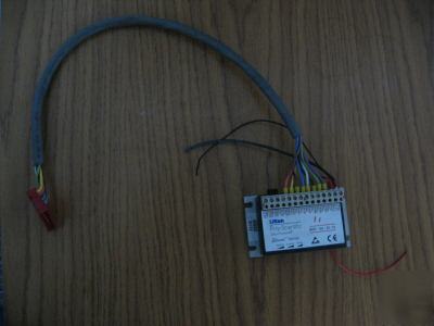
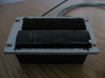
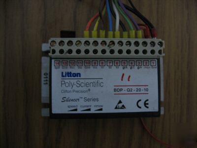
> Litton ply-scientific silencer bdo-Q2-20-10 lot of 10
Litton ply-scientific silencer bdo-Q2-20-10 lot of 10
â„¢ Series Brushless Controllers
2-quadrant speed controller for brushless motors
~Used but Pulled from Working Environment~
• The BDP-Q2-50-10, BDP-Q2-20-10 controllers are 2-quadrant speed controllers for
electronically commutating three-phase brushless motors with Hall sensors, which are
arranged offset at 120 electrical degrees
• The speed of the motor is preset by means of either an internal or an external
• The maximum constant current can be adjusted via an on-board potentiometer
Direction of rotation of the motor can be preset by means of the Direction control
input. The controller output stage can be activated and deactivated by means of the
• The controller is safeguarded against heat overload by means of an internal thermal cutoff
• The controller output stage has been constructed using POWER-MOSFET technology,
resulting in very high efficiency
Optimum heat dissipation is achieved by mounting the BDP-Q2-50-10, BDP-Q2-20-10 controller on a heat sink, and
through the use of a thermal conduction paste.
For longer distances between the motor and the control unit, > 12 in. (30 cm.), shielded cables should be used for the
sensor cable and the motor cable.
Operating voltages exceeding the specified values, or reverse connection will destroy the controller and will void the
Unauthorized opening and improper repairs will put the user in danger and will void the product warranty.
If the controller is brought from a cold environment into the operating environment, there can be condensation. Wait
until the controller has reached the ambient temperature of the operating environment, and is absolutely dry before it
(REV) open collector / TTL / CMOS / switch
(DIS) open collector / TTL / CMOS / switch
Storage -104 to 185ºF (-40 to +85°C)
Operation -50 to 113ºF (-10 to +45°C)
ELECTRICAL DATA BDP-Q2-50-10 BDP-Q2-20-10
-+input and Gnd 20-50 VDC 12-20 VDC
Maximum constant current (adjustable)* 10 A 10 A
Supply voltage for Hall switches 6 V/20 mA
For technical application assistance:
(***)-577-8685 ext. 256 • (***)-837-5115
MECHANICAL DATA BDP-Q2-50-10 BDP-Q2-20-10
(L x W x H) - 2.17 x 3.70 x 1.54 in. (55 x 94 x 39 mm)
4 x M3 with a distance between holes of 1.54 x 3.43 in. (39 x 87 mm)
BDP-Q2-50-10, BDP-Q2-20-10 SPECIFICATIONS
* at higher input voltages, additional heat-sinking may be required for maximum current
Control inputs 12 (Reverse), 11 (Disable)
can be enabled either by an external switch, an open collector transistor,
or by means of TTL/CMOS components. This connection is made to
SELECTING MOTOR DIRECTION-OF-ROTATION
Reversing the direction of motor rotation is easily accomplished. Using a switch, relay contact, or simply a jumper
wire, connect the terminal labeled
Rev. to the terminal labeled Gnd.
NOTE: Do not reverse motor direction while the motor is rotating. The controller is not designed for
Motor speed may be controlled via one of the following three methods (see page 4 and 5 for detail instructions):
1. On-Board Speed Potentiometer
2. External Speed Potentiometer – (Recommend 10k – 10 Turn Precision Potentiometer)
Control input Input open or high level Input on Gnd or low level
Rev Turning to the right (CW) Turning to the left (CCW)
Dis Controller active Controller inactive
For technical application assistance:
(***)-577-8685 ext. 256 • (***)-837-5115
Terminal # Nomenclature Description
2 Positive Input Positive Supply Voltage
9 VCC Supply for Hall Switches
11 DIS Control Input - Disable
12 REV Control Input - Reverse
14 SPD Set value input for speed
Disable input rather than setting the speed
potentiometer to zero. Some drift may occur even at zero setting of the speed potentiometer; this will not be the case
The following is a procedure for using each of the speed control methods mentioned on page 3.
1. On-Board Speed Potentiometer
A. Place a jumper from terminal labeled
D.Apply the operating input voltage across
+ Input and Gnd, being careful to observe polarity.
Do not apply an incremental input voltage, but rather a single step voltage.
E. Motor should now be running at full speed. Measure and record speed.
nmax trimpot CCW until the motor speed decreases slightly, then slowly rotate the
CW until the motor is once again running at full speed (see value recorded in step E).
nmax trimpot is now “tuned†to the motor currently connected to the controller and will not require
readjustment unless a different motor is connected to the controller, or the level of the input voltage
H.Motor speed may now be varied by using the
2. External Speed Potentiometer (optional)
See Figure 1 for connection diagram for External Speed Potentiometer.
External Speed Potentiometer fully CW
D.Apply the operating input voltage across
+ Input and GND, being careful to observe polarity.
Do not apply an incremental input voltage, but rather a single step voltage.
E. Motor should now be running at full speed. Measure and record speed.
nmax trimpot CCW until the motor speed decreases slightly, then slowly rotate the
CW until the motor is once again running at full speed (see value recorded in step E).
nmax trimpot is now “tuned†to the motor currently connected to the controller and will not require
readjustment unless a different motor is connected to the controller, or the level of the input voltage
H.Motor speed may now be varied by using the
3. External Voltage Control (optional)
By applying a DC voltage between
14 (Spd) and 13 (Gnd), the following conditions are observed:
speed range in control operation
no pulse-width-operation-control works in simple commutation mode
D. Speed potentiometer should be fully
nmax trimpot CCW until the motor speed decreases slightly, then slowly rotate the
CW until the motor is once again running at full speed (see value recorded in step E).
nmax trimpot is now “tuned†to the motor currently connected to the controller and will not require
readjustment unless a different motor is connected to the controller, or the level of the input voltage
Connection Diagram for External Speed Potentiometer
For technical application assistance:
(***)-577-8685 ext. 256 • (***)-837-5115
Note: The controller shuts down automatically when the temperature at the inside of the heat sink exceeds 80°C.
Proper overcurrent protection (fusing) is required for the protection of this controller. We recommend a
fuse. This fuse should be connected in series with the + Input line going to the controller and
should be of a value less than or equal to the maximum current rating of the controller (Max. Right Position).
Considerations regarding the power supply:
> 12 V and < + input with a residual voltage of < 5%
Output Current:corresponding to the necessary torque and possible reserves for acceleration
Procedure for calculating the necessary minimum supply voltage:
(S1, S2, and S3), as well as the Hall voltage supply (Vcc and Gnd) of Hall sensors.
3. Connect the control inputs according to the requirements
5. Set up the speed control for the controller
(depending upon which method of speed control is used -
6. After completion of step #5, speed control is now active.
7. Set the maximum current via the on-board speed potentiometer
For technical application assistance:
(***)-577-8685 ext. 256 • (***)-837-5115
Type Max. Left Position Max. Right Position
Brush and Brushless, Single and
Multispeed, Pancake and Housed
• Coupled to R/D converters, they provide a
digital interface to computerized motion
±7’ accuracy standard, ±3’ available for single speed
• 400-10,000 Hz frequency range standard
• Arc second accuracies are standard for
Limited angle rotation (LAR) (toroidally wound)
ALSO AVAILABLE FROM LITTON POLY-SCIENTIFIC
• Standard NEMA frames in 1.2†to 4.15†diameter
• Continuous torques range from 2.4 to 519 oz-in
• Compact size - lengths range from 1.3†to 5.5â€
• Standard options include gearheads, resolvers,
Permanent Magnet DC Brush Motors
• Standard NEMA frames in 1.31 to 4.0†diameter
• Long-life, replaceable brushes
• Gearmotors available in most frame sizes
• Up to 560 oz-in continuous torque
• Up to 3,500 oz-in peak starting torque
• Long-life, replaceable metal graphite brushes
• .125†and .187†inch diameters
• Continuous torques from 7.5 to 13 oz-in
• Encoder and tachometer packages
• Up to 1274 oz-in peak starting torque
• Continuous torques from 12.6 to 41 oz-in
• High torque per dollar ratio
• Standard options include electronic drivers, encoders,
and gearheads. Hall effect, resolver and sensorless
• Torques from 6 oz-in to 14 lb-ft.
• Tachometer and potentiometer options available
• Housed motors or as separate rotor/stator sets
• Options include gearheads, brakes, resolvers and
• Available with rare earth magnets
Commercial Brushless & Brush DC Motors and Military/Aerospace DC Motors and Resolvers
economical, highly accurate motion
information for closed-loop electronic
control, as well as brushless DC
motor commutation. They contain no
internal electronics or optics and are
unaffected by heat, electrical noise,